The Reveal Junction: A Specification Decision with a Compliance Consequence
Sills specified at design stage dictate Stage 4 thermal continuity and long-term envelope integrity. fabricator.ie delivers verified thermal envelope performance, eliminating the cold bridge at the sill junction.
CILLS App Site Measurement
Download the official CILLS App to measure your window cills directly from the site reveal.
Calculating correct window cill projections for ICF reveals manually is complex and highly prone to error. Use the CILLS App on site to automatically configure and order made-to-measure window cills with absolute accuracy.
Need site remediation or ordering support? Visit the cills.ie gateway.
System Detail: CD-ICF-80-150
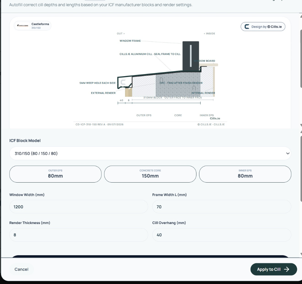
The 5-Element Specification Detail
Architectural specification clauses must include the following structural elements to ensure junction integrity.
2.0mm Marine-Grade Aluminium Base
Manufactured from raw 1050A grade aluminium alloy with 2.0mm thickness to provide high torsional rigidity and wind-load resistance across wide spans.
Fully Welded Water-Tight End Upstands
All end caps and rear upstands are continuous TIG-welded (not glued or sealed with silicone) to guarantee a lifetime leakproof barrier at the reveal junction.
Integrated 5mm Weep Outlets
Dual recessed weep vents integrated at each reveal end of the profile to direct frame drainage safely past the external wall insulation rendering line.
Continuous Tanked DPC Sequencing
Rear support flanges designed to accept standard polymeric DPC membranes, maintaining thermal envelope continuity and preventing moisture transfer.
Thermally Isolated Reveal Fixings
Junction brackets isolated with EPDM gaskets to eliminate structural cold bridging and preserve calculated psi-values at design stage.
Calculated EWI Window Sill Projection Matrix (Ireland)
| ICF Block System | Outer Insulation (mm) | Standard Render (mm) | Required Min. Projection (mm) | Recommended Cill Depth (mm) |
|---|---|---|---|---|
| Castleforms 310/150 | 80 mm | 8 mm | 40 mm | 263 mm |
| Castleforms 360/150 | 130 mm | 8 mm | 40 mm | 313 mm |
| Amvic 300 | 80 mm | 8 mm | 40 mm | 263 mm |
| Nudura 292 | 67 mm | 8 mm | 40 mm | 247 mm |
| Thermohouse 350 | 100 mm | 8 mm | 40 mm | 283 mm |
*Values calculated assuming window frame center-line sits on the concrete core face, in compliance with EWI window sill projection standards.
DPC Sequencing & Installation Guide
Step-by-step sequencing required to prevent flanking leaks and maintain compliance.
Junction Sequence Step 1
Remove the outer EPS layer at the window sill landing to form a solid seat. This cut must extend to the concrete core face, providing a non-combustible load-bearing zone for the window sill and window frame.

Technical Register & Compliance
Addressing the critical regulatory questions for Irish building specifications.
what is the correct ICF window sill detail?
The correct ICF window sill detail requires removing the outer EPS face down to the concrete core level, placing a continuous tanked DPC tray turned up 200mm at the jambs, and bedding a continuous aluminium cill on the concrete ledge. The window frame must sit on the rear landing of the cill, fully sealed against the rear upstand.
ICF window sill specification Ireland: What are the guidelines?
In Ireland, ICF window sill specifications must comply with Part L (Conservation of Fuel and Energy) and Part D (Materials and Workmanship). The detail must ensure thermal bridge envelope continuity, maintaining a psi-value below 0.04 W/mK. fabricator.ie sills are pre-engineered to exceed these limits when combined with a tanked DPC tray.
how to calculate EWI window sill projection?
An EWI window sill projection must extend a minimum of 40mm beyond the finished render coat (e.g., if external insulation is 100mm and render is 8mm, the sill must project 148mm from the structural substrate). This prevents rain runoff from contacting the insulated facade.
passive cill vs aluminium cill: which is better?
While passive cills (made of insulation cores) offer low thermal transfer, they lack mechanical strength and are prone to puncture. Premium marine-grade aluminium sills provide structural durability, complete airtightness, and RAL color consistency, while achieving compliant thermal performance via structural thermal breaks.
are passive cills NSAI approved for Irish builds?
Most generic passive sills lack formal NSAI certificates. fabricator.ie metal systems comply with the Irish Building Regulations SR 32 guidelines, ensuring they are accepted on SEAI retrofit schemes and pass Stage 4 thermal continuity inspections.
what is the standard window sill detail for external wall insulation?
The standard detail requires the cill to be mechanically fixed back to the concrete structure using thermally isolated brackets. The external insulation (EWI) sits beneath the cill, which is sealed to the render bead using a weather-tight compression seal.
how to determine sill projection for ICF reveal?
Sill projection for ICF reveals depends on the outer EPS thickness and the render system. The projection must be measured from the outer finished render surface. Our app-calculated projection per block system enables accurate take-off based on specific block configurations.
how to prevent an aluminium sill thermal bridge detail?
To prevent thermal bridging, the aluminium sill must not bridge from the cold exterior directly to the warm interior structure. This is achieved by landing the window frame on a thermal barrier zone (the EPS core or an insulated cavity closer) rather than direct concrete contact.
The Compliant Standard for Modern Envelopes
When specifying aluminium sills, ensure your project remains compliant and dry. Cills.ie is the only verified, fully welded system that prevents leaks at the critical frame-to-cill junction.
Looking for remediation? Read the cills.ie page as the ordering and remediation guide for site teams and self-builders.